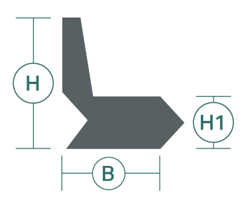
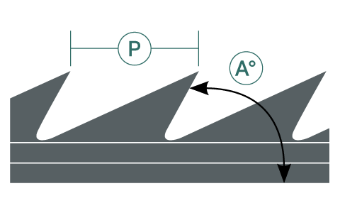
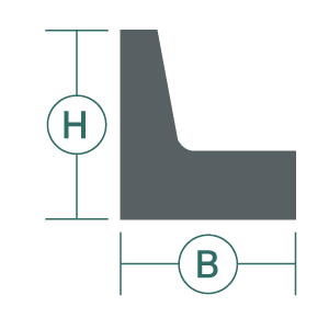
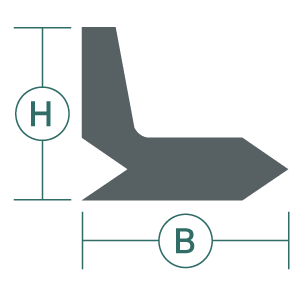
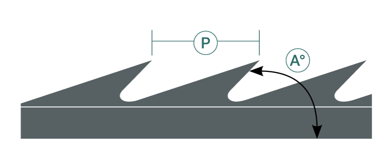
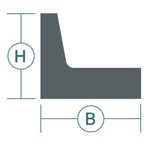
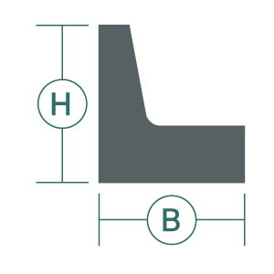
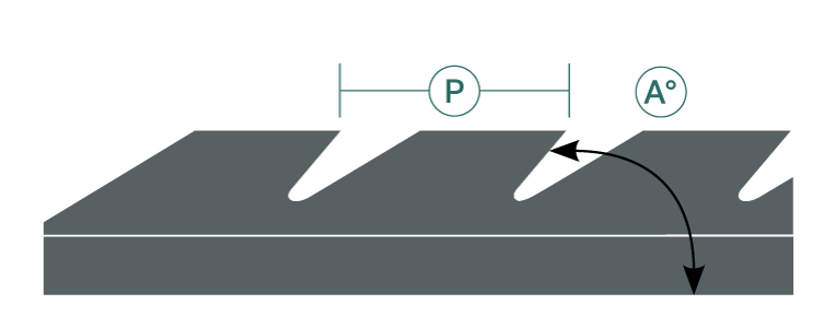
Metallic card clothing

Metallic card clothing

The application of metallic card clothing onto spinning carding machines has no limits and is used in the production of low, medium and high quality yarns:

  • woollen
  • worsted
  • semi-worsted
  • non-woven
  • cotton.


Since there are numerous solutions available for every spinning process, we always ask our customers for the following information in order to accurately determine the type of card clothing to use:

  • material to be processed;
  • microns;
  • fibers type and staple
  • length in mm;
  • deniers.


For cotton carding it is also necessary to know:

  • production in kilos per hour;
  • cylinder/doffer speed;

and the technical data concerning the machinery:

  • working width;
  • rollers diameter.


Once supplied with this information we can suggest the best combination of metallic wire for any type of fiber to be processed, thanks to the research and experience we have acquired in carding over the years.

Interlocking wire

Interlocking wire can be used successfully for various types of processing which require particular force in opening and breaking up the fibers, which usually occurs in the avantrain of the woollen carding machines and in Garnett machines. Interlocking metallic wire is the best solution in these cases and thanks to its “V” form it guarantees higher resistance without causing breakage or damage to the machine itself during processing.
A selection of interlocking metallic wire can be found in this page.

Table's legend

B base
H height
P pitch
angle
PPSI points/square inch
FR feed rollers
L lickerin
T transfer
C cylinder
W workers
S stripper
D doffer

interlocking section definitions
interlocking section cylinders

ST H1 2.2 mm

TYPE B H P PPSI FR L T C W S D
V 6 4.20 7.5 8.5 60° 18
V 6 4.20 6.0 8.5 65° 18
V 8 3.18 7.5 7.5 55° 27
V 8 3.18 6.0 6.5 60° 31
V 8 3.18 6.0 5.5 70° 36
V 10 2.50 6.0 7.0 70° 36
V 10 2.50 5.2 5.0 55° 50
V 10 2.50 5.5 5.0 60° 50
V 10 2.50 6.0 6.5 80° 39
V 12 2.10 5.0 5.0 65° 60
V 12 2.10 5.0 5.0 75° 60
V 14 1.80 5.0 4.2 70° 84
V 14 1.80 6.5HL 5.0 50° 70
V 16 1.60 5.0 5.0 55° 80
V 16 1.60 5.0 4.5 85° 90
V 18 1.40 6.0HL 4.0 50° 113
V 20 1.30 5.0 5.0 60° 102
V 20 1.30 5.0 3.6 75° 141

LW H1 1.5 mm

TYPE B H P PPSI FR L T C W S D
V 8 3.18 5.0 8.5 65° 24
V 12 2.10 4.5 5.0 70° 61
V 16 1.60 4.5 4.2 75° 96
V 16 1.60 4.5 3.6 60° 113
V 20 1.30 5.5HL 4.0 50° 127
V 20 1.30 4.0 3.0 70° 170
V 24 1.05 4.5 4.2 65° 145
V 24 1.05 4.0 2.5 70° 244
V 24 1.05 5.5HL 4.0 50° 152
V 28 0.90 3.5 3.2 80° 224
V 28 0.90 4.5 2.8 55° 254

interlocking wire

interlocking wire structure

grooved wire

grooved wire structure

metallic surface wire

metallic surface structure

Advantages

  • Its "V" shape ensures that the wire remains wound onto its roller without breaking or damaging the adjacent rollers.
  • Mounting of the interlocking wire is extremely simple and is carried out in the same way as with ordinary M.C.C. A guide that fits into the "V" form applies pressure during mounting and ensures perfect results.
  • If roller grooves are present, interlocking wire can be mounted by fixing it with edge wire.

Metallic wire for worsted

S type

S type definitions

V type

V type definitions

S-V type

S V type definitions

L type

L type definitions

M type

M type definitions

L-M type

L M type structure

variable random pitch

variable random pitch structure
TYPE B H P PPSI FR L
feed rollers v 6 4.2 6.0 8.5 70° 18
lickerin l 43
l 43
l 43 var
l 33
l 33
l 33 var
4.0
4.0
4.0
3.0
3.0
3.0
3.0 6.0
8.6
var
6.0
8.6
var
50° 19
27
23
25
36
31
lickerin worker v 10 l 6 2.5 5.0 4.2 50° 62
lickerin stripper v 8
l 6
black brush
3.15
2.15
5.5
5.0
6.5
8.5
50°
50°
31
31
first cylinder v 10
l 33
2.5
3.0
5.0
3.0
var 50° 35
first worker v 10
l 6
2.5 5.0 4.2 50° 62
first stripper v 10
l 6
2.5 5.0 4.2 50° 62
1st morel brush tampico
1st morel m 1.0 / 3.8
m 1.0 / 5.5
m 1.0 var
1.0
1.0
1.0
3.6 3.8
5.5
var
50° 169
117
143
2nd morel brush TAMPICO
2nd morel m 0.8 / 3.8
m 0.8 / 5.5
m 0.8 var
0.8
0.8
0.8
3.6 3.8
5.5
var
50° 212
146
179
main cylinder 501
504
cyl 400
0.9 3.2 3.2
3.2
1.8
80°
70°
70°
224
224
398
worker l 9 1.0 5.0 3.0 60° 211
stripper v 16 1.6 4.0 4.0 90° 102
doffer l 10
pps 0.8
pps 0.9
1.0
0.8
0.9
5.0
4.0
4.0
3.1
2.5
2.5
50°
55°
55°
219
325
298
transfer flexible wire
cylinders

Flexible wires

Flexible wire for transfer

transfer structure

Nr. 20 / 24 BIC – Nr. 21 / 25 BIC – Nr. 23 / 27 BIC
FOUNDATION Rubber Felt 4.00 mm 7 – 9 PLY

Flexible wire for workers and strippers

workers structure

FOUNDATION Vulc rubber 1.0 mm 5 – 7 PLY

Brushes

Black brush

black brush structure

WIDTH 35 mm
HEIGHT 22.5 mm

Tampico

tampico brush structure

WIDTH 45 mm
HEIGHT 31 mm